Daemons - Ocean Force
- thomas (Unlicensed)
With this daemon it is possible to translate the information of an ocean statistical spectrum or a displacement map into forces. An ocean statistical spectrum, or just OSS, is a method of creating absolutely realistic waves structures. The main purpose is to apply waves of different sizes to a Hybrido fluid surface, but “Ocean Force” also affects standard SPH particles, Hybrido secondaries, and rigid/soft bodies.
When you add an “Ocean Force” daemon you will see a long list of parameters. Experienced users will immediately recognize that the parameters belong to RealFlow's OSS – it is exactly the same method as you can find with RealWave's OSS modifier, under Hybrido or in RealFlow's graphs system – they are all based on exactly the same implementation. If you have worked with the OSS method before you will be able to start directly. New users should read the parameter descriptions below.
How to Work with the “Ocean Force” Daemon
By default, you can see a wavy height field in RealFlow's viewport. This “icon” represents the ocean statistical spectrum based on the daemon's current parameters. This preview helps you to evaluate this wave structure visually. If you prefer other visualization methods you can also switch to a force map or disable this feature completely under “Preview Type”. A way to show the actual forces is to use the daemon's “Display Force Field” function. For more information about how to use this preview option please follow this link.
As mentioned above, you will mainly use this daemon to displace a fluid surface and create wave structures – preferably a Hybrido surface. Start with a basic Hybrido scene:
Add a Hybrido domain.
Create a container to maintain the fluid, e.g. a “Cube top open” object, and rescale it to your needs. Change Node Params > Volume > Volume mode to “Solid outside”.
Apply a “Cube” node, adjust it to the container's horizontal size, and adjust its vertical scale to a value between 0.5 and 1.0.
Add a Hybrido emitter and link the “Cube01” node to it. This object represents the space where the fluid is being created.
A “Gravity” daemon can be found under Edit > Add > Daemons.
The “Ocean Force” daemon is also located under “Daemons”.
Once all elements have been added, the daemon can be adjusted. For this purpose there are preview modes (“Preview Type” option) giving you an idea of how the OSS will look. All changes to the OSS parameters affect the preview directly.
- Scale and position the daemon's box/viewport preview so it fits the fluid's/objects' outlines, because the force will only be applied inside the volume indicated by the dashed lines. All areas outside this box will not be affected.
- Adjust the remaining parameters and simulate.
- Create OpenGL previews to compare the results.
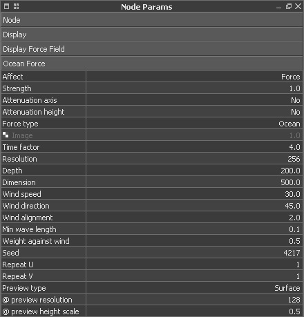
Affect
Particles can be affected in two ways: either by “Force” or “Velocity”. The first option applies an external force, resulting in an acceleration, while the second one only modifies the velocities of the particles without introducing an additional acceleration. Forces take a little time to display their full influence. This means that they accelerate the particles over a certain time span depending on their strength. High forces exert stronger accelerations and the particles or bodies become faster and faster as long as the force acts on them.
“Velocity” directly affects the particles from the very beginning without any delay or deceleration. The result is an apparently stronger influence, because the deflection of the particles starts with the very first moment. “Velocity” is not available for rigid bodies.
Strength
Here, the daemon's strength is adjusted. All positive and negative values are accepted.
Attenuation axis
If you do not want the forces to decrease over space just leave “No”. Otherwise you can specify how the forces should diminish along a certain axis. There are three options available: “Linear”, “Square”, and “Cubic” – the latter option is the fastest method.
Attenuation height
The daemon's force attenuation can be adjusted for the spectrum's/map's height information separately. With “No”, the forces will not decrease. Otherwise you can specify how the forces should diminish with “Linear”, “Square”, and “Cubic” – the latter option is the fastest method.
Force type
The standard type is “Ocean”. When this mode is active, RealFlow calculates a force from the position changes in the statistical spectrum. With “Ocean”, the spectrum's vertical displacement is used to scale the forces.
Instead of the built-in statistical spectrum is also possible to use image maps. These maps can be displacement maps from RealWave, Hybrido, or other sources, but even custom-built images are supported. For “Image” you will need at least two images, because only then will RealFlow be able to calculate a force from changes in position. “Image” uses the well-known principle of displacement maps: the map's pixel intensities are translated into values which can be used to generate height information, or – as in this case – forces.
Image
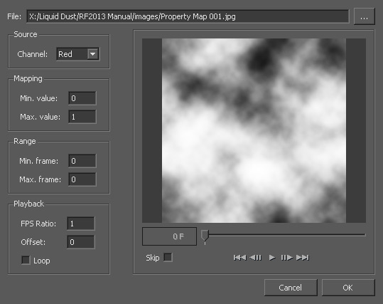
This parameter field is only accessible when “Force type” is set to “Image”. To load an image (sequence), right-click on the small chess board, and choose “Load image”. Then, a new dialogue appears. For a detailed description of the features and parameters of this panel, please take a look at the “Mapped Parameters” chapter below.
Time Factor
If you have already worked with RealFlow's Graphs system or one of the demo scenes, e.g. “apply_stat_spectrum” then you have most probably already seen the “Time factor” setting. This parameter allows you to control the wave surface's speed. Values greater than 1.0 will accelerate the waves, while values smaller than 1.0 can be used to decelerate them. The advantage is that the waves' speed can be adjusted without changing any other parameter. Another plus is that the “Ocean Statistical Spectrum” settings from RealFlow Graphs, Hybrido, and RealWave have been unified as far as possible. This way, you will be able to get exactly the same results with identical settings in all three environments. "Time factor" is a dimensionless value and accepts floats – it works as a multiplier.
Resolution
You can choose from seven different levels of quality. Of course, higher quality settings require longer simulation times, but also create more details. This parameter is dimensionless and only accepts the predefined values from the select list.
Depth
This parameter affects the dispersion of the waves and is only noticed if the length of the wave is close to the value of the depth. In these cases this parameter has a decelerating effect on the wave's dispersion. In most cases you will not see any effects or changes, because depth is normally rather high compared to the length of the waves. The parameter's unit is metres [m].
Dimension
This value acts like a scaling factor and is given in metres. With a value of 500, the distribution and scale of the waves will look as if the domain covers a squared area of 500 m x 500 m, although the physical dimensions of the domain did not change at all. When you change “Dimension” you will most probably have to modify “@ preview height scale”. “Dimension” and “Resolution” are directly connected:
Level of detail [m] = Dimension [m] : Resolution
An example: Let’s assume you have created a surface with “Dimension” of 400 m and a “Resolution” of 1024. The smallest structures will have a size of 0.39 m according to the formula above:
400 m (Dimension) : 1024 (Resolution) = 0.39 m
Wind speed
You can enter any positive or negative value, including 0. “Wind speed” can strongly influence and affect the look of the surface. The parameter's unit is metres per second [m/s].
Wind direction
This is the wind direction in degrees. If you use an axis setup, where Y does not serve as a height axis, the orientation of the wind direction will change. With the default YXZ orientation, RealFlow uses this notation:
- 0°: wind comes from the positive X axis (1,0) - positive wind directions are counter clockwise.
- 90°: wind comes from the positive Z axis (0,1)
Wind alignment
This parameter is used to decrease the number of waves. With
- small values only waves which are totally perpendicular to the waves' direction are removed
- higher settings will remove more and more waves.
Min Wave Length
The amount of surface details can be controlled here:
- Higher values flatten the surface and create fewer ripples
- With smaller “Dimension” values this parameter should be decreased to guarantee that the surface still shows enough structures
Weight Against Wind
If “Weight Against Wind” is 0.0 then all waves against the wind are eliminated. If it is set to 1.0 then its normal strength is used. Values between determine the amount of waves being eliminated.
Seed
A seed value is used to generate different initial conditions. This helps you to create different looks of the waves with a single click. You might already know this feature from RealWave's “Fractal” modifier. There you can also influence the waves with a new seed. This value is dimensionless and accepts integers.
Repeat U/V
Since the displacement is calculated from a texture map it is also possible to define the number of repetitions both in U and V direction of the mesh grid. U and V coordinates are related to the UV grid that is created with the mesh. Displacement maps are seamless, though very high values are very likely to create regular patterns on the surface. This value is dimensionless and accepts integers.
Preview Type
Here you can define how the force field should be displayed in the viewport. “None” disables the representation of the height field, but the domain's bounding box and icon are still visible. Their visibility is controlled under “Display”. “Surface” is the default option and shows the ocean statistical spectrum in a 3D viewport representation. “Magnitude texture”, on the other hand, visualizes the daemon's force field in the form of a coloured map: red indicates high forces, while blue colours stand for low forces.
@ preview resolution
The quality of the viewport's height field is adjusted with this parameter. You can choose from resolutions between 64 and 512.
@ preview height scale
If you want to decrease the height field's height in the viewport use a value smaller than 1.0. With settings greater than 1.0 the spikes become higher.
Mapped Parameters
You have already read that many parameters can be represented with image maps – here is some additional information. Image maps create areas of different influence, based on the colours of a bitmap or texture. The adjustments are made from a separate window, providing all relevant parameters and switches to make use of this feature. An additional function is that you are even able to load image sequences for animated parameters. Dark areas indicate zones with low values, while white represents the maximum.
Especially larger objects can strongly profit from this feature. You can, for example, create a river bed with low “Particle Friction”, while the outside areas have higher values. All this can now be painted to a map and then projected onto your object. This does not only work with RealFlow’s native items, but also with imported objects from SD files. It is important that imported objects carry (correct) UV coordinates.
It is even possible to make the used map or image sequence visible in RealFlow’s viewport. If you cannot see it, or work with multiple maps for different parameters, you can easily to show the desired map with:
Display > Texture > [ Map type ]
If you want to replace the fixed value with an image map, please do the following:
Right-click on one of the parameters with a chess board icon.
Choose “Load Texture” from the context menu.
RealFlow opens a new window called “Load Texture for Parameter”.
Fill out the dialogue and confirm your settings with “OK”.
File
Under “File” you can load one or more image files with TGA, BMP, JPG, PNG or TIF format. The path to the image is shown under File. With the “…” button it is possible to open your OS’s file picker. The images must be coloured – either 8 bit, or if supported, also 16 bit. Image sequences are recognized automatically and you do not have to select the first and the last frame. All files with an equal padding are loaded to the canvas.
Channel
Here you can choose one of the picture’s RGB channels. The currently active channel is shown in the canvas and updated according to your selection. “Min. value” and “Max. value” are, by default, the pixels’ intensities. They are spread over the available minimum and maximum range of a parameter but, in case of need, this range can be clipped by entering new values. The shades of the image channel are then spread over the given settings.
Min. value/Max. value
The grey shades of the loaded image will be transferred into values ranging from “Min. value” to “Max value”. So, the lowest grey tone will get the value from “Min. value”, and the highest grey tone receives the value from “Max. value”. All the other grey scales are calculated automatically between the given minimum and maximum.
Please bear in mind that the maximum value is 1.0 and “Min. value” cannot be greater than “Max. value”. This feature is also very interesting if you see problems like local instabilities or exploding particles. This can often be observed with very high “Particle friction” settings. In such a case, simply decrease “Max. value”, e.g. to values around 0.1.
Min. frame/Max. frame
These values are important for image sequences. You are able to specify a certain frame range that is used for parameter mapping. Simply enter the desired start and/or stop value and the frames outside of this range will be ignored.
FPS Ratio
With a value of 1 the image sequence is played at its original speed, e.g. 30 FPS. If you want to achieve faster or slower playback then you have to change "FPS Ratio" accordingly. Values above 1 will increase playback speed; smaller values are used to slow it down.
Offset
If you do not want to start with the first frame of your sequence, you can determine an “Offset” from which the series will start playing.
Loop
This option creates an infinite back and forth loop from the currently loaded image series.
Control buttons
They work exactly as in other video players. You can go to the first or last frame, to the previous or following frame, and start/stop playback. The slider allows you to scrub through the entire sequence and jump to a certain frame.
Skip
Finally, the “Skip” option is related to “FPS ratio”: while playing back an animated sequence, RealFlow cannot always achieve the given FPS rate. By checking “Skip”, RealFlow will play the image sequence with the adjusted FPS rate, but some images might be dropped. Without “Skip”, RealFlow shows all images, but there is no guarantee that the desired frame rate can be maintained.