Maxwell Mesher
- Systems Next Limit (Unlicensed)
- Next Limit
- Anonymous
With complex scenes, meshes will allocate a huge amount of disk space. Together with particle BIN files, even large disks can quickly reach their limits. Today mass storage is one of the cheap components of a computer system - however, the sheer amount of data can often lead to problems. Also, some 3D packages simply cannot handle very large meshes.
Maxwell Mesher bypasses these limitations by creating meshes directly during the rendering process. In other words: the meshes don't have to be created inside RealFlow™ anymore and will allocate just a fraction of the disk space. MXS export times are also greatly reduced allowing for much more efficient rendering of animations.
The Maxwell Mesher, is based on the RealFlow RenderKit v3 (RFRK3) advanced on-the-fly meshing engine, uses state-of-the-art technology, such as multi-threading, and advanced smoothing technology to achieve a natural fluid look, which shares the same parameters as the RenderKit meshing engine in RealFlow 2014. All the features you know from RealFlow, like clipping or filtering, are also available with the Maxwell Mesher making it a powerful, versatile and fast tool for render time mesh creation.
Courtesy of Taek Won Young
These are the parameters to control the rendering of the particle cloud. Many settings are identical with their counterparts inside RealFlow, but there are also some unique values, and the individual parameters are differently grouped. It is applied as an extension object (i.e. in Studio, you can load it on Object>Create Extension Object>MaxwellMesher. In the supported plugins, its location depends on each 3D platforms interface).
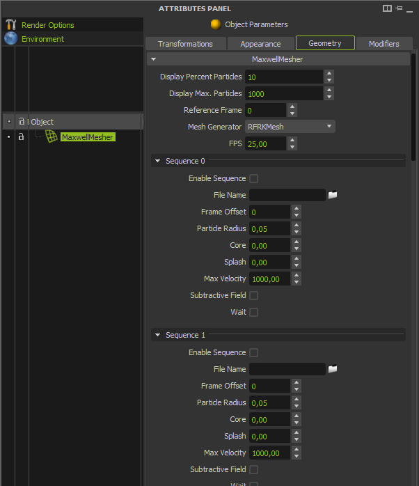
MaxwellMesher panel (detail)
The Sequence sections
This panel provides everything you need to load and manage particle sequences. It's possible to load more than one sequence, and you can either create a separate MaxwellMesher object for each file pool or combine them within an object.
Sequence and File
This is where you can see the full paths to the currently loaded BIN file sequences. Please note that this field only shows the sequences which are attached to the active MaxwellMesher item. For each series of BIN files, a new Sequence tab will be added, making it possible to adjust the basic settings independently. Sequences from other mesher object will be displayed under their appropriate mesher object. The frame number indicated by the Reference Frame value, and all the frame offsets will be applied over this reference frame.
Offset
You can specify any positive or negative offset here that will be applied to the particle sequence.
Radius
Fluids with large gaps between particles require a larger radius to fill these spaces and create a homogeneous surface. The problem with these low-resolution fluids is that they look artificial, have round borders and show this typical “blobby” look. These fluids often appear like muddy substances and they can intersect surrounding objects. Even filtering cannot remove all these unwanted side-effects completely; the only effective method to enhance the mesh is to use a much higher emitter resolution.
In other words: you'll need many more particles to fill the gaps and create a smoother fluid surface. Instead of a higher emitter resolution you can also use the Sheeter daemon (in RealFlow) to fill the holes.
On the other hand it's also possible to literally “erode” a fluid surface with very small Radius values. In combination with small Polygon Size settings, the fluid will look unnatural. These meshes can also be filtered and smoothed, but we recommend that you adjust the Radius value before playing with filters. The best meshes are those which only need a very low amount of post-processing.
Radius is not just a dimensionless or abstract parameter, but has world scale units (regarding your scene units).

How to find the perfect Radius
Fluid particles can be described as tiny droplets or spheres; this value determines the radius of these spheres. When the individual spheres are very close, they'll start blending into each other. This is not just a simple intersection - the amount of blending is calculated by the mesh engine and depends on the distance between the particles and, of course, the adjusted radius. The result is a smooth and organic hull around the particle cloud – at least when all parameters are adjusted correctly.
The main problem, especially for beginners, is to find a good balance between Polygon Size, Radius and the emitter's resolution. A good idea is to start with similar values for Polygon Size and Radius and adjust Radius gradually until you've found the optimal settings. Another method is to use the given default values and decrease/increase them according to your requirements. No matter which workflow you use, once you're satisfied with your mesh you can start to filter the fluid's borders.
Creating meshes requires a little experience and maybe you'll find a completely different workflow. For beginners the presented method is a very good start to get quality results without spending too much time on trial and error. Finding the perfect radius mainly depends on two factors: testing and experience. A very small radius will show much more detail (if there are enough polygons, e.g. small Polygon Size value), because the individual spheres won't be so blended. The result is often a very turbulent surface where you can see almost every drop. Smoothing and filtering can reduce these effects. Higher Radius settings will decrease the level of detail, because the spheres become bigger and start interpenetrating each other.
Another side effect with higher Radius values is that the fluid borders become thicker and show an – often unwanted – rounded look. The “Relax” filter is able to reduce this effect, but you do have to be careful, because strong filtering can produce an artificial look like liquid metal with high surface tension. Of course, the best radius is a good balance between blending and detail, but this is, as mentioned before, a matter of experience. You will soon learn which Radius values work best for calm or turbulent fluids. Then you will only have to perform some minor adjustments and add moderate filtering to smooth the fluid's borders.
Core filter
The Core and Splash filters values are used to separate the fluid into two individual zones based on a particle's number of neighbours. With these two parameters it's possible to easily create a fluid body with surrounding splashes or foamy areas. You simply enter values for the core fluid and the splashes to differentiate between these two states. The advantage is that both core and splashes can be meshed with different parameters. For the coherent core fluid you can create a rather smooth surface, for example, while the splash parts are much more turbulent. Core and Splash are also a very convenient way to edit and process your meshes without recalculating them.
The Core value ranges between 0.0 and 1.0 and can be adjusted independently from Splash. A value of 0.0 means that the entire fluid will be seen as the core fluid and you can't observe any changes in comparison to a “normal” mesh without these filters. 1.0 removes the complete mesh. With increasing values the mesh will start shrinking.
 Splash filter
Splash works the same way as Core, and you can enter any value between 0.0 and 1.0. With 0.0, the whole fluid body will be treated as one big splash. Like Core, the mesh becomes smaller with increasing Splash settings. When both parameters are set to 0.0, the filters have no influence on the mesh and are deactivated.

Max. Velocity
In some cases it's necessary to clip the particles' velocities, because some particles have accelerated too much. Normally, these particles should be deleted with appropriate daemons, but sometimes they're still part of the simulation. The problem with these particles is that motion blur effects are mainly influenced by velocity and misbehaving particles can falsify the results or even lead to useless renders. With Max. Velocity, all speed values will be clipped to the specified setting which represents the maximum velocity for your render. This is an easy and effective method to control the motion blur streaks.
Do not forget to enable the motion blur in the Maxwell Render settings.
Substractive
This type of operation (“Boolean operation”) is well-known from 3D programs and allows you to combine or subtract objects to create new shapes. The Maxwell Mesher also supports boolean operations and allows you to load multiple particle BIN files and blend them together.
By default, all existing particles in your scene will be merged together to create one coherent mesh. If you have ever used RealFlow's NBinary Loader, then you'll immediately understand the idea behind this feature.
The NBinary Loader allows you to combine particles from different emitters and treat them as a single source. Boolean operations inside the Maxwell Mesher work in a similar way. You can also combine the particles from different emitters. The result is mesh that looks as if it was made from a single emitter. Another great option is to mix RealWave files with particles and create one mesh from these obviously inhomogeneous sources. This feature allows you to make seamless meshes from splashes, emerging from the RealWave surface after the impact of an object or a boat wake.
It's not only possible to merge different particle files - they can also be subtracted. When you tick this checkbox, the appropriate particle sources will be considered as subtractive.

Two fluid sequences together. The image on the right shows one fluid with "Subtractive" activated.
Wait
The creation of the meshes is done actually at render time, while the BIN files come from RealFlow. This workflow allows you to perform the fluid simulation on computer A, for example, and do the rendering on computer B simultaneously. With Wait, the render engine stays idle until the next BIN file is available. Then, the render process will continue with the new particle file.
The Mesh section
Creating believable meshes with enough detail, but low polygon counts, is not always an easy task. Fortunately, this internal meshing engine is very economical in terms of computer resources and parameters. MaxwellMesher produces accurate results with minimal settings and provides fast mesh generation due to its sophisticated multi-threaded algorithms. The main problems concern thick borders, a wrong scale and an insufficient amount of detail.
Polygon Size
This is another parameter that directly influences the quality of the mesh and is responsible for its level of detail. The smaller this value, the more polygons will be added to represent the fluid's shape. As with any 3D object, increasing the number of polygons leads to larger files and higher memory allocation.
Polygon Size only affects how many details you can finally see, so if you want to capture all the little splashes and drops of a fluid then rather low values (0.03 – 0.01) should be used. In some (rare) cases, for example for fluids with relatively small particle numbers, it might also be necessary to decrease Polygon Size to values lower than 0.01. To avoid an unnatural look, please consider Smooth or filtering. Depending on the fluid cloud's size and number of particles, the RFRK2_Mesher can create several million polygons.
Please keep in mind that the number of polygons is not responsible for a fluid's characteristic look, like water, honey or liquid metal, since Polygon Size doesn't have any influence on the mesh's borders or speed stretching effects.
These characteristics have to be adjusted and corrected with the Smooth parameter, filtering and a sufficient amount of particles.

Smooth
As commented on the previous paragraph, this parameter, as its name suggests, is used to finish a mesh's surface and create a more organic, fluid-like look. The parameter blends the spheres and metaballs together to achieve a coherent look.
Auto Polygon Size
With this mode, the MaxwellMesher mesh engine automatically adjusts Polygon Size to achieve the best balance between quality and the number of faces. Nevertheless, the result will always be based on a mathematical model and not on your own visual impression. We therefore recommend that you use this function for your first tests on mesh creation, because it can be used as a starting point for more detailed settings. To see which Polygon Size value the engine has used for Polygon Size you can have a quick look at the logs of your renderer. There you'll find the desired information.
Field Type
There are two fundamental types to generate a mesh:
- Sphere, which is the default setting
- Metaball
Both methods can lead to rounded fluid borders. To compensate for this unwanted look you can increase the “Smooth” value and/or decrease “Radius”. Another, even more effective method is to use the “Relax” filter. The number of particles also plays an important role - with incorrect settings you can often see the individual spheres around the particles.
Axis
This option tells Maxwell which axis will serve as the scene's height axis. You probably already know this issue from RealFlow's preferences panel. There, you also have to specify the correct setup for your 3D application. With the wrong setup, imported particles will be tilted around 90 degrees. There are three different modes:
- YXZ used by Lightwave or Cinema 4D
- ZXY used by 3D Studio Max or Maya
- YZX used by Softimage, Maya or Houdini
If the orientation of the imported particles or RealWave surfaces won't fit with your local axis setup, please consider changing this parameter. Please note that Maya offers a left-handed and right-handed system and hence you can find two options.
The Filters section
In RealFlow, a particle is actually nothing more than a tiny virtual sphere in space. To make their positions visible, it's common to display them as dots, crosses or little spheres, for example. When we want to represent the particle cloud as a coherent fluid mesh, it's necessary to add some volume to the particles, filling the space between their individual positions. The idea is to define a certain radius for the particles so that they can really be seen as spheres with a particular dimension. The size of this sphere is defined with the “Radius” parameter (as described above). The mesh engine finally blends these spheres together to achieve a smooth fluid.
The principle behind this method is easy to understand. If you just have a few thousand particles, you'll need a much higher radius to “connect” the particles, and you'll most probably see the individual spheres after the meshing process. The result is a coarse and “blobby” mesh without many visible structures. When you add more and more particles, the simulation becomes more detailed and you can decrease the particles' radius to achieve a coherent mesh. With enough particles, the individual spheres won't be visible anymore, because the mesh engine can blend them together and apply some smoothing.

The problems of this method can be seen at the fluid's edges (see image above), because there, we can still observe the influence of the spheres, creating more or less strongly-rounded borders. Isolated splashes, holes or small groups of particles often show the same issue.
Filters can reduce this rounded look and create a more natural fluid, just as we would expect from real liquids. The RFRK2 filtering methods should be considered with almost any mesh. Though they are the most effective way to enhance your meshes, it's important to be careful with these parameters, because with filtering you can completely change the characteristics of a fluid. What was water before can then even look like liquid metal.
Filter Mesh
This checkbox is used to switch the filters on or off globally for the currently active particle sequence, for example if you want to evaluate the influence of the used filters. The advantage with this checkbox is that you can preserve the already-made adjustments when you want to turn off the filters.
Relax
This filter type is the right choice when you want to remove the rounded borders of a fluid mesh. The default value of 0.3 is always a very good starting point and in most cases you don't have to change it. Instead of playing with Relax, it's often better to adjust Steps. With very high Relax values it's possible to create very sharp-edged meshes with a mercury-like look or structures similar to a sponge.
Relax is very effective and some filtering should be considered with any mesh, though low-resolution simulations will profit more from it. With very low amounts of particles, even high settings won't help, so please always make sure that your simulation has a sufficient number of particles.
If you have high Smooth values, Relax should also only be changed within a moderate range to keep the fine detail of your fluid simulation.

Tension
In some (rare) cases, fluids show unwanted ripples or surface structures which cannot be removed. Sometimes it's not possible to re-simulate the scene, because of a tight deadline. If you ever happen to see this behaviour, you should try to flatten these patterns with the Tension filter first. If you cannot get rid of them, then it's time to consider a new simulation with moderate drag forces to slow down the particles' motion. Like Relax, Tension is also a very sensitive filter and should be changed carefully. A starting value of 0.1 – 0.2 will be sufficient for most applications. Again, it's also better to work with Steps, instead of Tension, so you can keep this value fixed.
Steps
Both filters, Relax and Tension, are influenced by this parameter. It tells the mesh engine how often the filters will be applied, so high settings will lead to more filtering. High resolution simulations require fewer samples, and the more particles a scene contains, the fewer steps are normally needed. Good initial settings range between 16 and 64. With values greater than 120 you'll mostly observe very sharp fluid borders.
The Clipping section
Fluid simulation is a complex business and in many cases it's necessary to simulate parts which will be finally invisible to the scene's camera. This can happen when you want to flood a room, for example, and larger parts of the particle cloud are simply hidden behind a wall or the fluid comes from the outside of the scene. By default, these invisible particles will be considered for the final mesh and may contribute hundreds of thousands of actually useless polygons. These polygons can drastically increase render times and will always bloat the mesh file. To thin out your files and meshes, MaxwellMesher provides an easy, though very effective method: clipping. There are two methods which can also be used simultaneously.
Object Clip
You can use any geometry/object to clip a mesh, but simple primitives work best, because they don't need too much calculation time. Clipping with boxes or low-resolution objects is a fast way to remove invisible parts of a mesh. Of course, you can choose whether you want to remove polygons from the inside or the outside of the clipping object with the Inside checkbox.
To clip a mesh, MaxwellMesher requires at least one SD file. Please keep in mind that all objects inside the SD file will be used for the clipping process. If you only want to use a single object, you have to prepare an appropriate file. You also have the option to load and use more than one SD file using the SD File field.
The workflow is simple:
- Tick Object Clip
- Load the desired SD file(s)
- Create the mesh during rendering
Camera Clip
Camera clipping is another method to discard polygons. In this case, everything that's outside the current camera view will be deleted, so you'll get a perfect view-dependent mesh. The best thing is that you can even use Object Clip and Camera Clip together.
This combination will drastically decrease the number of polygons and accelerate rendering.
Inside
This option is only available for Object Clip and has no influence on Camera Clip, because it simply makes no sense to cut out the polygons within the camera's field of view. Checking this button tells the mesh engine whether it should remove the polygons inside or outside the object(s) from the specified SD file. The result is always a closed mesh, because this function is able to detect holes or open parts and fills them with new polygons.
SD File
Open a file picker to load the desired SD simulation file.
The Optimization section
Similar to the RealFlow mesh engine, it also provides optimization algorithms to reduce the number of polygons. An optimization process always removes polygons and the resulting mesh will be different from the original, of course. We therefore recommend that you perform a few tests with different parameters to make sure that the optimization process won't remove important details.
Optimize
There are two fundamental techniques:
0. None, disables the optimization process.
1. Curvature, which is based on a mesh's curved areas and this mode tries to keep them while flat areas will be removed, at least partially
2. Camera, which analyses the mesh based on the polygons' distance to the scene's camera. Areas close to the camera will keep a high level of detail and regions which are far away will be optimized. This mode is adaptive and also works with moving cameras. This guarantees that the currently focused parts of the mesh can always be rendered at high quality.

Quality
Higher settings yield better results, but at the cost of calculation speed. You can enter any value between 0 and 1, though very small settings can strongly influence the quality of the mesh and lead to unwanted results.
Reduction
This parameter provides a very convenient and plain method for reducing the mesh's number of polygons just by defining a percentage value. An example: by entering a value of 75, this function keeps approximately 75% of the original polygons and deletes the remaining 25%. So, a mesh with 100,000 faces will have around 75,000 polygons left after optimization. Please keep in mind that these values are only approximations, since it's actually impossible to specify the exact amount of polygons; the tolerance can therefore easily be several thousand polygons depending on the total number of faces.
Distance
This value represents the distance between the camera and the area where the first polygons will be removed. With greater distance (= higher values) the number of polygons decreases. The area with the highest resolution is always nearest to the camera. For many scenes, Distance is the most effective way of reducing the number of polygons. In combination with camera clipping, it's a very powerful tool and you should always consider using it.
The RealWave section
RealWave is RealFlow's wave generator, and offers a wide variety of surface modifiers to create all kinds of realistic waves. These surfaces are very easy to control and even the most complex waves and interactions can be simulated within a very short time. Basic setups can even perform in real time on modern computers. To give you the possibility to render these structures, the RFRK2 offers an easy method to import and mesh RealWave files.
The idea is to create seamless meshes from splashes emitted from a wave surface. In other words: this function combines particles (splashes) with geometry (wave surface).
To make use of RealWave files it's important to become familiar with the different file formats, because not all file types are supported. Basically, there are three main formats: RWC, SD and BIN.
- RWC is a pure cache format (RealWave Cache) and only used internally by RealFlow. Please note that RWC is the default format for wave meshes and you might have to change the export options under RealFlow's Export Central dialogue (for more information about Export Central, please visit the RealFlow documentation).
- SD stands for “Scene Data” and is RealFlow's standard file format for geometry and animation exchange. Since RealWave surfaces are actually nothing more than displaced and animated geometry, SD is a suitable file format. While individual RWC and BIN files are saved each frame, SDs contain all the information written into one single file.
- Finally, there are BIN files from particles and mesh sequences, created by RealFlow. BIN is a very flexible format that can be used for many different data types and information. Though particle, mesh and RealWave BINs share exactly the same extension, there are fundamental differences in how the data are stored.
Insert RealWave
Ticking this checkbox will tell MaxwellMesher that there's a RealWave object in your current scene. To make use of this option, you also have to load the RealWave SD file on the RW File field. .
RW Polygon Size
Like any other RealFlow mesh, a wave surface also has a specific polygon size. This parameter must contain the polygon size of the original RealWave mesh. RealFlow's default value is 0.1. This parameter strongly influences the quality and level of detail of the RealWave surface. Small values show more wave details, while higher settings are often used for large ocean surfaces or distant shots.
Resolution
This parameter determines the quality of the final RealWave mesh. A RealWave surface already consists of triangles, and the number of polygons is indirectly controlled with the Polygon Size parameter in RealFlow. Resolution tells MaxwellMesher how many particles will be distributed in the triangles. Higher values produce smoother meshes, but they need longer to render and allocate more system resources.
The illustration below represents a part of a RealWave mesh and shows you how this feature works. The blue dots represent particles, the orange triangles are polygons. Higher Resolution values are used to subdivide the surface, creating a smoother mesh.

Radius
MaxwellMesher uses the RealWave surface's vertices to create particles and the Resolution parameter adds more particles to enhance quality. Again the result is a particle cloud that can be meshed. Radius has exactly the same function as its counterpart described on the Sequence section above. Though both Radius settings share exactly the same background and functionality, the settings for meshes and RealWaves don't have to be identical. They can be treated separately from each other and mainly depend on the number of particles.
RW File
Open a file picker to load the desired RealWave SD file. Please note that MaxwellMesher only accepts SD files – other formats are currently not supported.
The BIN Mesh section
Loading a BIN mesh (sequence) with the MaxwellMesher extension is different from the method that's provided by the RealFlow plug-ins. With the plug-in BIN mesh loader you'll see the imported mesh in the program's viewport, but not so with this tool. Here, the mesh will be directly sent to the render engine. The loaded mesh will act just like Lazy Compute and still contain all magnitudes, but there's one very important difference: this feature overrides any existing particle BIN file sequences and ignores all previously made settings. The only possible settings are related to shading and texturing.
Insert BIN Mesh
This box works like the ones you've seen under the Clipping or RealWave sections, for example. Checking the box globally activates or deactivates this feature. The advantage is that all previously settings will be conserved, so when you switch Insert BIN Mesh on again, you won't have to repeat the loading process.
BIN File
Open a file picker and select and load the desired BIN mesh file.
Bin Frame# Offset
As with all parameters based on file sequences, it's also possible here to define a frame offset. Both positive and negative values are accepted.
Wait
With this function it's possible to stop the rendering process until the specified mesh file is available. This feature is very convenient, especially when you perform simulation and rendering on different computers, since you don't waste any time: the simulation can still be in progress while the render process runs simultaneously.
The System section
You can fully customize not only your mesh settings, but also the system specifications, to decide how many resources will be allocated by MaxwellMesher and how the data will be passed to the render engine. The size of a mesh depends on a variety of parameters, but it can easily exceed 50 or 100 MB. Especially with heavy scenes, large amounts of particles or low Polygon Size values, mesh files will rapidly grow in size. Some 3D programs cannot handle these huge meshes and fail to render. To avoid this problem, MaxwellMesher internally subdivides the mesh into parts that will be rendered separately. The result is still a seamless mesh - you won't notice the subdivision process. Though the entire procedure is completely automated, you have the option to control it manually.
Threads
This option is only relevant for users with multi-processor systems. Here you can specify how many threads should be used as a maximum for mesh creation.
Memory (MB)
MaxwellMesher can subdivide large meshes into seamless matching parts. This feature helps to prevent memory or stability problems with very large polygon counts. This parameter allows you to define a limit for the maximum size of each sub-mesh in megabytes.
The "Export and Lazy Compute" section
Once you have found the working settings for a mesh, the next step is to apply and adjust an appropriate material or shader. This workflow normally requires a more or less large number of test renderings; it would be very time-consuming to create a new mesh each time you have to alter one of the material's parameters. With very large meshes this workflow is not very economic and so Export and Lazy Compute can be used to write out a file without sending any data to the render engine. It's then possible to load the mesh as a proxy and make your material settings.
Working with proxy meshes is definitely the most convenient and fastest workflow when you have to apply a large number of changes. Even if the proxy mesh only has a low resolution, this is still enough to give you an impression of how the material settings will finally influence the render quality.
Action
This function offers three options:
0. Off, turns off the feature
1. Export, is used to write an MD file to disk
2. Lazy Compute, reads a previously exported MD file for shading purposes.
The MD format written by MaxwellMesher is fully compliant with RealFlow's own MD files, and you can also use files directly from Next Limit Technologies' fluid simulation program.
MD File
Here you can specify the path to the MD file. The format is “path/rfrkmesh#####.md” and the “#” characters will be substituted by the current frame number. If you want to use an MD file from RealFlow, its name has to be changed according to this format.
MD Frame# Offset
You can also determine an offset (frame number) for the loaded mesh with this function. Both positive and negative values are accepted.
Blend material
When you load more than one particle sequence into the same MaxwellMesher object (to be meshed together), you can now give each fluid a distinct look, by using just one multi-layered material. These distinct fluid material layers can even be blended in the transition between two fluids.
You can download a sample of this material sample here.

Two fluid sequences loaded with the same MaxwellMesher and using a blend material
Simply create a multi-layered material, and use each layer to define each individual fluid. Then, on each material, use a horizontal black-to-white ramp texture as the Layer weight.
The UV channel that you use on each of these ramps is very important: The layer whose ramp you assign on channel 1 will be the material of the fluid mesh #1. The layer whose ramp you assign on channel 2 will be the material of the fluid mesh #2, and so on.
The smoothness of the transition between two fluids is defined by the smoothness of the black-to-white ramp.

Use a black-to-white horizontal ramp to define the transition of two fluids in the blend areas

This layer will be applied to the fluid loaded in Sequence #1 (Channel 1). The ramp controls the transition between this material and the others.
