Daemons - Force Field Falloff
- thomas (Unlicensed)
- Alex Ribao
This set of parameters is not available for all daemon types. With falloffs it is possible to fade a daemon's forces and control exactly how they should vanish.
For a workflow description please go to
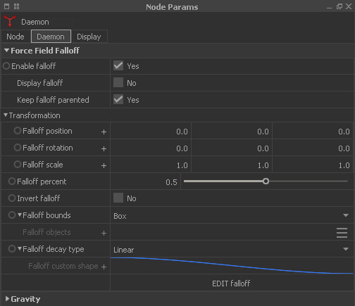
Enable falloff
When set to “Yes” the falloff feature is active.
Display falloff
Activate the checkbox and you will see a viewport gizmo in the form of two yellow boxes. The space between the boxes determines the falloff area. Strictly speaking it is a falloff volume, but "area" gives you a better idea. This gizmo can be configured freely:
- With different “falloff options” the gizmo will change accordingly to a sphere or plane, but the mode of operation is still the same.
- We recommend activating the → “Show field” option under “Display Force Field” for monitoring how your settings affect the forces.
Keep falloff parented
When active the falloff area, represented by the falloff gizmo, will follow the daemon's position, scale, and rotation changes.
Falloff position
The falloff area's position in space, defined through X, Y, and Z components. All values are given in metres. Click on “+” for sliders.
Falloff rotation
The falloff area's rotation in space, defined through X, Y, and Z components. All values are given in degrees. Click on “+” for sliders. Rotation can be used to get interesting effects.
Falloff scale
The falloff area's scale, defined through X, Y, and Z components. All values are given in metres. Click on “+” for sliders.
Falloff percent
This value is used to increase or decrease the falloff area – the inner falloff limit is represented by a dashed cube/sphere; the outer limit is the bigger box/sphere:
- Values should range between 0.0 and 1.0 (maximum).
- Negative settings are also valid and can be used to extend the falloff area beyond the gizmo's outer limit.
- The greater the value, the earlier the force falloff starts.
- With 0.0 the falloff area is 0 as well – the gizmo cubes/spheres have exactly the same size.
Invert falloff
By default the falloff goes from the gizmo's inner box/sphere to the outer box/sphere, but it can be inverted with this option.
Falloff bounds
Your options are:
- “Box”. This is the standard representation and the space between the two cubes defines the falloff area.
- “Sphere”. Instead of two boxes you will see the two spheres.
- “Object". Here, an object is used to calculate the falloff's shape. The associated object(s) are specified under "Falloff objects".
Falloff objects
When Falloff bound > Objects is active you can choose one or more objects to calculate the falloff's shape.
Falloff decay type
Your options are:
- “None”. The forces end abruptly and there is no smooth transition.
- “Linear”. The forces fade out smoothly.
- “Quadratic”. The forces will vanish faster than with “Linear”.
- “Cubic”. The forces will vanish even faster.
- “Custom shape”. Create your own decay by drawing a curve under “falloff custom shape”.
Falloff custom shape
When “falloff decay type” is set to “Custom shape” you can create your own falloff curve. The parameters and options are explained separately directly below.
Falloff custom shape
The curve is only evaluated when “falloff decay type” is set to “Custom shape”. A click on “+” reveals an editor and several parameters to shape the blue curve.
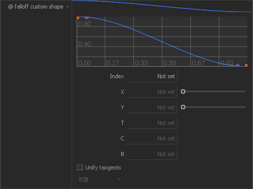
The horizontal X axis represents the falloff area (the area between the two boxes/spheres):
- 0.0 (min) represents the falloff areas inner boundary.
- 1.0 (max) is the falloff areas outer boundary.
The vertical Y axis is a force multiplier and determines the force's strength at a certain point.
- 0.0 (min) means that the resulting force will be 0.0 as well.
- 1.0 (max) means that the resulting force is equal to the daemon's strength value.
Drawing and shaping curves is easy:
- Add new control points with a double click.
- Select control points with a click or draw a rectangle around them.
- Drag points with the mouse – the corresponding X and Y values are displayed below.
- When the point's type is “Bezier” it is possible to drag the tangent handles.
- Bezier tangents can be manipulated individually by deselecting “Unify tangents”.
- Delete control points with right-click > Remove control point.
Index
When a control point is selected you will see its index here.
X | Y
These values represent a control point's X and Y values. You can enter values manually for fine-tuning the curve.
T | C | B
The tangents of “TCB” control points are adjusted with these three parameters:
- T(ension). Lower settings produce smooth and rounded curves with slight ease effects.
- C(ontinuity). Higher values produce a curved overshoot; negative settings create a sharp change in the curve's direction.
- B(ias). High values create a (more or less) linear curve.
- All positive and negative values are allowed, including 0.
In | Out
The tangents of “Bezier” control points are manipulated with these two parameters individually:
- “In” is responsible for the control point's left tangent.
- “Out” is used to adjust the control point's right tangent
- All positive and negative values are allowed; 0 creates a vertical tangent.
Unify tangents
When this option is active both sides of the Bezier tangents have the same gradient. When disabled the tangents can be manipulated individually.
Control point types
All control point types can be mixed freely:
- “TCB”. This type uses three parameters to adjust a control point – tension, continuity, and bias.
- “Bezier”. This type uses tangents to adjust a control point. Tangents are manipulated with the mouse in the editor or the “In” and “Out” parameters.
- “Linear”. This type connects the control points with straight lines.
- “Step”. This type creates an abrupt change between two control points similar to a stair.