Texture Mapping: UV and UDIM
- Systems Next Limit (Unlicensed)
- Anonymous

Render courtesy of Wieger Poutsma - FISK Imaging (www.fisk-imaging.com). Client: 361º Sports
Texture mapping defines the way a tridimensional object is mapped into the bidimensional space of a texture. It is basically the mapping from a 3D space (where the vertices have three coordinates) into a 2D one (where they only have two, horizontal and vertical). Normally this step is prior to the texturing phase, in which the model needs to be unwrapped into a 2D coordinates system that defines how the texture fits onto the object.
There are basically two types of texture mapping: the traditional UV mapping and the newer UDIM and other Tiled Texture formats.
UV Mapping
The traditional UV mapping process assigns each vertex of the model a position on a bidimensional space, in which the horizontal and vertical coordinates (named U and V respectively) vary from 0 to 1. The texture image is created according this spatial distribution, so the color of each vertex on the model (in fact, its texture coordinates) can be derived from the position of the vertices on the UV map. Out of the 0,1 boundaries the texture image will be repeated.
UV space
UDIM and other Tiled Texture formats
UDIM (developed by Foundry's Mari) and other Tiled Texture formats are basically an evolution of the UV concept. The main drawback of the traditional UV map is that you can not have different mapping resolutions for each part of the model. If you have one single UV map for the entire model, and a specific part of the model needs to be highly detailed, for example the face, you are forced to make the entire body texture at that high resolution, creating large files unnecessarily.
Instead, these Tiled Texture definitions make use of more tiles of the mapping space, which allows to unwrap different parts of the model in different spaces, and assign independent texture files for each one according to the resolution needed.
For instance, the UDIM space is composed of 10x9999 individual grid tiles (10 in U and 9999 in V) instead of the traditional single tile in the UV mapping.
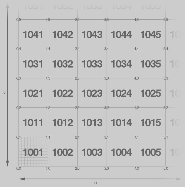
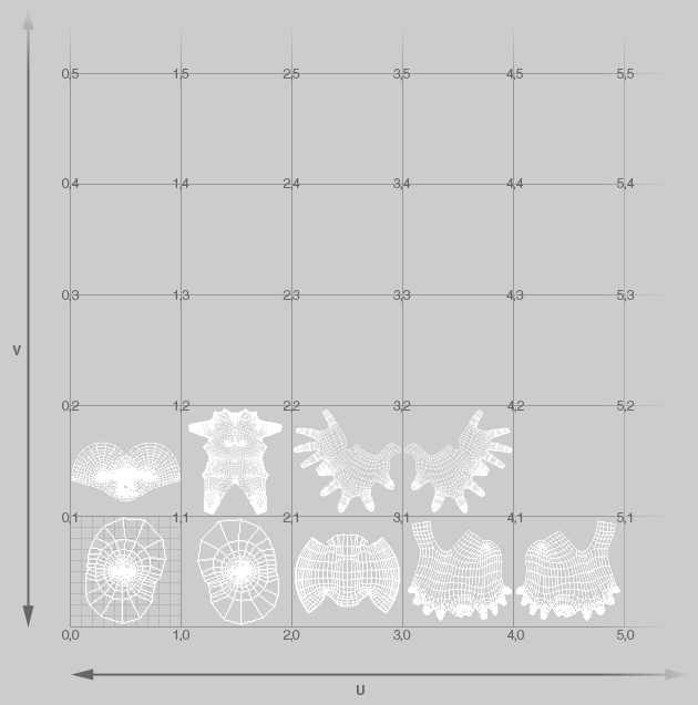
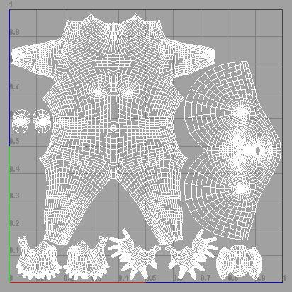
The first 25 tiles on a UDIM space (left). A model unwrapped on a UDIM space (right). Now the texture file corresponding to each tile can have independent resolution and detail.
As you can see in the scheme above, the UDIM convention specifies that the tiles must be identified by a numerical ID that defines its location, from 1001 to 9999. All the textures used by the model need to append the corresponding numerical ID on their name, so the mapping can find automatically the one needed. In the example above, instead of one generic bump file, you will have a collection of 9 independent bump files, stored in the same folder and named according to the tile distribution, i.e.: character_bump.1001.tif, character_bump.1002.tif, character_bump.1003.tif, character_bump.1004.tif, character_bump.1005.tif, character_bump.1011.tif, character_bump.1012.tif, character_bump.1013.tif and character_bump.1014.tif.
Using Tiled Textures in Maxwell
In Maxwell, UDIM support and Tiled Textures comes as a procedural texture. To apply your textures according to this format, simply apply a TiledTexture procedural on the corresponding texture slot, input one of the texture files and specify the numerical ID appendix format you are using (Filename mask). Maxwell will automatically recognize them all and apply the correct file to the corresponding piece of geometry.
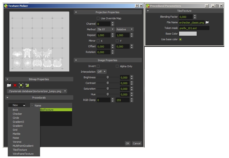
Applying UDIM textures
Parameters
- Blending Factor: Blend percentage of the current texture with the result of the others below in the procedural stack.
- File Name: Inputs the path to the texture files.
- Filename mask: Defines the format in which the tile numerical ID is present in the files naming. For this purpose, there are several predefined tokens to specify the tile indices position in the file name (<udim>, <u>, <v>, <U>, <V>, <u2>, <v2> and <U2>, <V2>), as it is described in the Info section below.
- Base Color: Defines a plain color to be used on the tiles in which no texture were found. The use of this color is enabled with the Use base color checkbox.
Naming conventions and tokens
While the way to enumerate the tiles can be completely customized, there are some conventions already accepted by certain softwares.
- UDIM convention
The UDIM standard convention uses the four digits nomenclature described above. Under this convention, the texture files look like this:
mytexturename_1001.ext
mytexturename_1002.ext
mytexturename_1003.ext,...
In this case the Filename Mask needs to be: mytexturename_<udim>.ext
- <u><v> convention
This convention separates the u and v tiling indices and enumerates them separately, starting at zero. Under this convention, the texture files look like this:
mytexturename_0_0.ext
mytexturename_0_1.ext
mytexturename_1_0.ext,...
In this case, the Filename Mask must be: mytexturename_<u>_<v>.ext
Some softwares use this convention but inserting a "u" and "v" letter for a more explicit identification, naming the files: mytexturename_u0_v0.ext... As the "u" and "v" letters are in fact part of the name, the Filename Mask here should be: mytexturename_u<u>_v<v>.ext
Note: The <u><v> convention uses only one digit, starting at zero, to enumerate the tiles. When two digits were needed, the tokens are replaced by the <u2> and <v2> tokens.
- <U><V> convention
Similar to the previous one, this convention also separates the u an v tiling indices, but in this case the enumeration starts at one. The texture files look:
mytexturename_1_1.ext
mytexturename_1_2.ext
mytexturename_2_1.ext,...
To use this convention, the Filename Mask must be: mytexturename_<U>_<V>.ext
Note: the <U><V> convention uses only one digit, starting at one, to enumerate the tiles. When two digits were needed, the tokens are replaced by the <U2> and <V2> tokens.