GUI - Scale, Mesh, LOD
- thomas (Unlicensed)
These buttons contain a set of often-used functions. The annotations below explain these buttons from the left to the right:
![]()
Build mesh
This button is used to create a mesh for the current frame. You do not have to go to the mesh container’s settings any more to build a single mesh. Instead you can click on this button. Of course, there has to be a mesh object with at least one linked emitter available.
Interactive Meshing
A mesh node's features and options can be applied automatically when the "Mesh interactive" mode is enabled (which is not the case by default). This means that you do not have to rebuild the entire mesh to see the changes you have made, and the new mesh is updated in RealFlow's viewport without having to press a button. The live mesh option can be subdivided into two categories:
- Field-based parameters. When a mesh is built, a so-called field is created to describe the fluid's surface. This is the most time-consuming part of the meshing process. In a second step, the field is used to extract the polygon mesh, and that is a very fast procedure. The field-based settings include parameters like “Polygon size”, “Weight normalization”, and “Radius”. “Clipping” operations are also part of this category. When you change one of these parameters it will take a long time to get a result, because the field has to be recreated.
- Polygon-based features. In this case, only the polygons are updated, but the underlying field is not affected. Changes on these parameters are therefore applied very fast. Parameters of the second category are “Filters” and “Optimization”. Hybrido meshes also include the “Boundaries” and “Displacement” parameter sets.
To make use of this feature, a short workflow is necessary:
- Go to the frame of interest and enable Mesh shelf > Mesh interactive mode
- A mesh will be created automatically.
- Tweak your settings with live updates.
- Confirm these adjustments by creating a mesh with the “Build mesh” command.
- Mesh the entire sequence with Mesh shelf > Build Mesh Sequence
Scale options
With RealFlow you have the possibility of setting independent scales for geometry and daemon forces acting on fluids (Hybrido and particle fluids) and objects. Another option is to globally change the scale of the Hybrido domains' and objects' cell sizes, including mist.
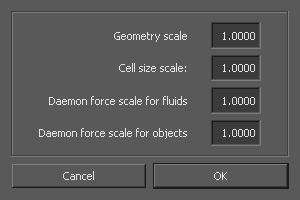
Geometry scale
If you want to change the scene's scale for the currently loaded project individually, please enter a new value. Please note that RealFlow will only scale geometry, but not emitters, domains or daemons. All these nodes have to be adapted manually once the scene's scale has changed. In most cases it also necessary to adjust emitter resolutions or domain cell sizes. RealWave surfaces are not affected by “Geometry scale” as well. Daemon forces, on the other hand, do not have to be changed, because RealFlow's Caronte rigid and soft body solver is completely scale-independent.
Since different programs work with different scales, this scale type has to be represented in RealFlow’s workspace. Most of today's 3D programs also allow users to work at various scales as well (mm, cm, ft, m). RealFlow's standard scale, on the other hand, is 1.0 m. When RealFlow's scale is set to 1.0 m object with dimension of 20 cm x 20 cm x 20 cm, for example, appears in RealFlow with exactly the same size: 0.2 m x 0.2 m x 0.2 m. With a RealFlow scale of 10.0, the object appears as if it has a size of 2.0 m x 2.0 m x 2.0 m. Most of the connectivity plugins already provide a parameter where it is possible to adjust the objects to a certain scale, but this can also be done directly inside RealFlow with the "Geometry scale" parameter. The following conversion table helps you to find the correct factor if you want to refer to RealFlow's standard scale of 1.0 m:
| Scale | RealFlow Scale Factor |
|---|---|
| 1.0000 mm | 0.0010 |
| 1.0000 cm | 0.0100 |
| 1.0000 inch | 0.0254 |
| 1.0000 yard | 0.3048 |
| 1.0000 m | 1.0000 |
| 1.0000 km | 1000.0 |
| 1.0000 mile | 1609.3 |
1.000 means that there is no transition and the imported objects exactly share the same scale as RealFlow’s internal nodes. This is also important for exchanging RealFlow projects between users working with different scene scales. Scale is also connected to the viewport’s grid. One grid element has always a size of 1.0 m x 1.0 m, independent from the currently adjusted scene scale value.
Cell size scale
With Hybrido fluids, cell size is one of the most important parameters, because it affects all aspects of a simulation. In cases where fluid-object interaction is required, the objects' own “Cell size” value also has to be considered. Now imagine a scene with dozens or hundreds of objects with a default “Cell size” of 0.3 and you want to change this value to 0.1. Instead of selecting all objects and changing this value, you simply alter “Cell size scale” to 0.333. The formula is:
Cell size scale = Cell size (new) / Cell size (current)
Of course, this new value also affects the existing Hybrido domains, not only the objects.
Daemon force scale for [ particle fluids/grid fluids/objects ]
This convenient feature allows you to scale all daemon forces globally for each solver type: SPH particle fluids, Hybrido grid fluids, and the Caronte solver. The idea behind these parameters is the same as with “Cell size scale”. Instead of changing each daemon individually, it is much faster and easier to determine a global value. Another side effect is that you can keep track about your settings much easier and all your changes can be redone with a single scale change again.
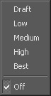
Visualization level of detail
With this option you will be able to define the quality of the displayed elements. You can choose from several levels – from “Draft” to “Best”. With “Off” you can disable this feature. It is important to know that the adjusted level of detail is only used during the simulation process. Once you stop and play back the cached information, everything is displayed independently from these settings.
Send to job manager
If you want to simulate non-interacting standard fluids, including splashes, foam and mist, on several machines independently, to speed up the simulation process, this is the right tool. The "Job Manager" works together with the new IDOC nodes. Another possibility is batch simulating: simply open a scene, send it to the "Job Manager" with this button, load the next scene, append it to the job list and so on. The simulations will be processed one after the other.
Send preview to job manager
The mode of operation is the same as with “Send to job manager”, but here a Maxwell Render job will be started, not a simulation. Of course, batch renders can be created as well.