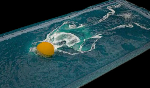
Channel Rendering
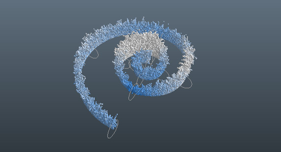
When you take a look at a particle simulation you can see differently coloured particles:
These colours
- represent the particles' individual velocities or another property
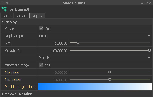
- can be customized in the emitter's or domain's “Display” panel
- are available for other channels (vorticity, age, etc.) as well.
Channels with Particles
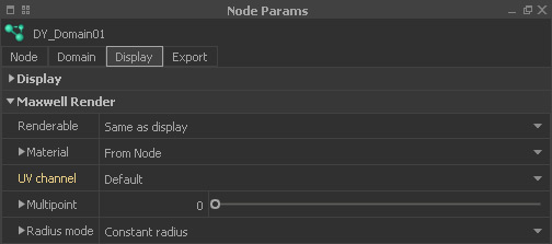
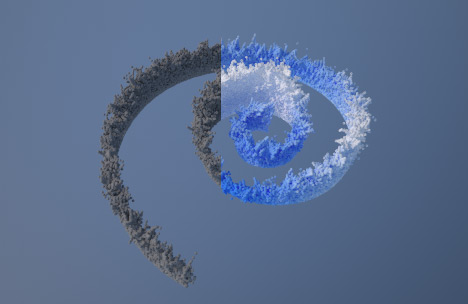
When you render the particles everything will be displayed with the node's default colour (see split image below). With “UV channel” it is possible to transfer the colour distribution to the rendered image. In conjunction with particles you simply have to choose a channel from
Emitter | Domain > Node Params > Maxwell Render > UV channel
Colours and ranges are changed under the emitter's or domain's "Display" panel with the "Particle range color" gradient and the "Min | Max range" parameters:
Then, start the render, e.g. with → “Maxwell Interactive” ("FIRE" button from the “Render” shelf). Here is a comparison of a fluid render without and with activated "Velocity" channel:
Channels with Meshes
The concept, described above, is also valid for meshes (except the legacy type), but the workflow is different, because a Maxwell material is required. All relevant settings are located under Mesh > Node Params > Maxwell Render:
- From “UV channel” choose the attribute you want to visualize, e.g. "Velocity".
- Adjust the → colour gradient under “Mesh range color”.
- Use "Range min | max" to enhance the channel's contrast.
Now, the material has to be applied. For this purpose RealFlow comes bundled with several predefined shaders. These shaders control how much of the gradient you will finally see – and this amount is based on the selected “UV channel's” attributes.
Material > choose one of the opacity map materials: "deep_ocean_foam", "clear_water", "atlantic_foam", or "muddy_waters".
Start → “Maxwell Interactive” ("FIRE" button from the “Render” shelf) or create a → final render from the current frame.
