Click here to see what's new in V3.2
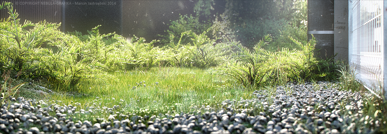
Image courtesy of Marcin Jastrzebski
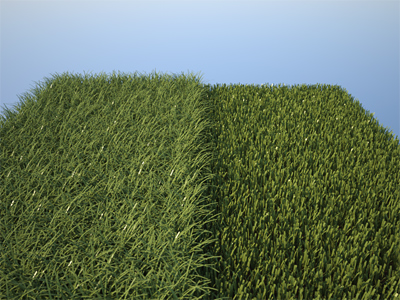
The Grass extension allows you to very easily and quickly create different types of grass. The extension is designed to offer you a great amount of randomization and control with many of the parameters also being mappable. Moreover, you can apply several different grass generators to the same object, which allows you to mix the look of different types of grass. You can create grass in Maxwell Studio and also in almost all of the 3D applications that have a Maxwell Render plug-in:
- Sketchup
- 3DS Max
- Maya
- Cinema 4D
- Lightwave
- Rhinoceros 3D
- Solidworks
- ArchiCAD
- form•Z
This extension consists of two different components:
- Grass Generator: Creates grass guide curves spread across the surface you choose, and controls their distribution, length, width, bend etc.
- Grass Primitive: three different analytic primitives to define the shape of the blade itself: straight flat segments, curved flat segments and cylindrical.
To quickly get you started, have a look at the Grass Examples page in the Knowledgebase section where you will find different examples of grass types and their settings, and also a couple of helpful textured grass materials ready to download and apply.
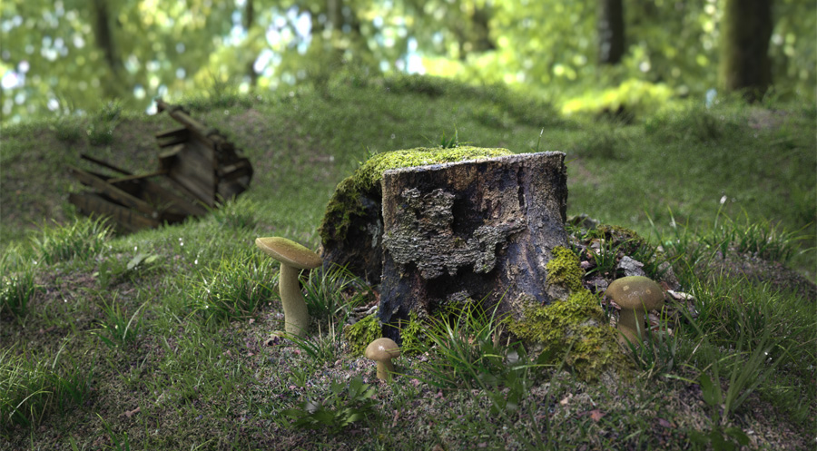
Image courtesy of Hervé Steff- Meindbender
The Grass Primitives
The guide curves created and distributed by the Grass Generator have to be replaced by a renderable geometry in order to present an actual surface that can handle a material description and be renderable. This happens at the beginning of the render, when the guides in the MXS file are replaced by one of the following Grass Primitives, that define the shape of each blade of grass.
Flat
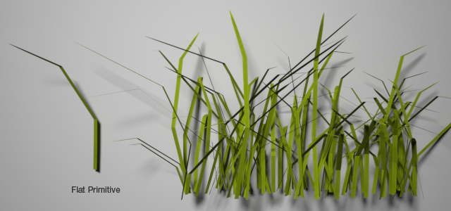
The Flat primitive renders a segmented flat strip, and the number of points define how many "segments" the rendered blade will have. The minimum number of points is 3. It's well suited for thin SSS materials since it's a single sided geometry.
The main advantage of this type is that it renders faster than any of the other grass primitives. For example you can create grass that is very close to the camera using the Curved type and apply a second grass primitive to the object for blades that are farther away from the camera. You can control where these two types of grass grow by using a density map.
As this primitive is made of straight segments, the number of Points per Blade define the number of straight segments in each blade. You may determine the number of segments you need depending on how it looks from your camera view. The more segments, the smoother the blades will look, but you will also increase the demands of RAM needed to render your scene.
Flat primitive using 4 points per blade
Curve
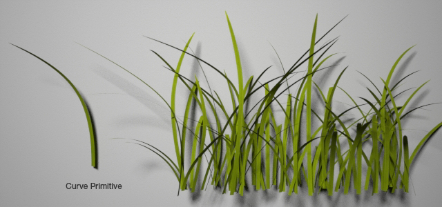
The Curve primitive renders a smooth curved blade of grass that has infinite detail - no matter how close the camera gets to a blade you will not see any facets or breaks in the curve. Similar to the Flat primitive, it's well suited for thin SSS materials, and perfect for close-ups and areas near the camera. You can specify the number of points that define the curve. 3 points is the minimum, 4 is a good number even for blades that bend a lot.
As this primitive is made of an analytic curved surface, it is smooth at each point, no matter how close you look at it. This means you don't need to increase the number of points too much to get a smooth blade. In general using around 4-6 points per blade is enough to perfectly define the smooth shape, without using too much RAM during rendering. Many more points than this is not necessary for the Curve primitive and will only increase the RAM usage without adding anything to the look of the blade.
The Curve grass primitive is slower to render than the Flat primitive. For this reason we suggest to always use the Flat primitive for the fastest renders and if the camera needs to be very close to the grass blades, use a separate smaller patch of grass that's close to the camera and use the Curve primitive for this patch.
Curve primitive using 4 points per blade
Cylinder
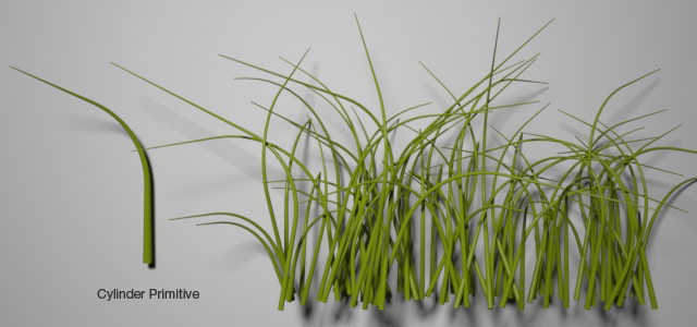
The Cylinder primitive renders each guide as a rounded cylinder, exactly the same primitive used by the MaxwellHair extension. It is well-suited for rounded grass, or even for generating fur and hair. The cylindrical fibers have an actual thickness and volume, so they can handle transparent and volumetric subsurface scattering materials.
As this primitive is made of straight segments of a cone, the number of Points per Blade define the number of straight cone segments in each blade. You may determine the number of segments you need depending on how it looks from your camera view. The more segments, the smoother the cylindrical blades will look, but you will also increase the demands of RAM usage that is needed to render your scene.
Cylinder primitive using 16 points per blade
Applying Maxwell Grass to an object
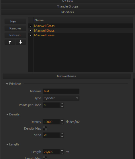
Simply select a piece of geometry and apply the MaxwellGrass modifier to it. You can do this either by right-clicking on an object in the Object List panel and choosing Apply Object Modifier Extension>MaxwellGrass, or you can click the New button in the Modifiers section in the Object Parameters panel. You will see the MaxwellGrass modifier and its parameters in that object's Modifiers section. You can also click the little white dot to the left of the modifier to disable/enable it. You can click the Refresh button when you have scaled the grass geometry to update the viewport so it shows the grass blades generated from the new size of the object. You can apply more than one grass modifier to the same object and each extension will use its own settings.
If you apply more than one grass extension to the same object, make sure each one has a unique seed number, to avoid having the blades growing from the same location.
Several MaxwellGrass modifiers being applied on the same ground geometry (screenshot from Studio)
Two independent grass modifiers applied together to the same ground geometry (hidden here) to create a more natural look by generating a mix of two different grass species
Texturing grass
Similar to the MaxwellHair extension, the grass can use UV channels 0 and 1 to map a texture from the root to the tip of the blade (channel 0) and across the surface of the object (channel 1). Any Maxwell material can be applied to the grass, except of course glass and volumetric subsurface scattering materials, as these need a thickness in the geometry to render properly, and will only work with the Cylinder primitive.
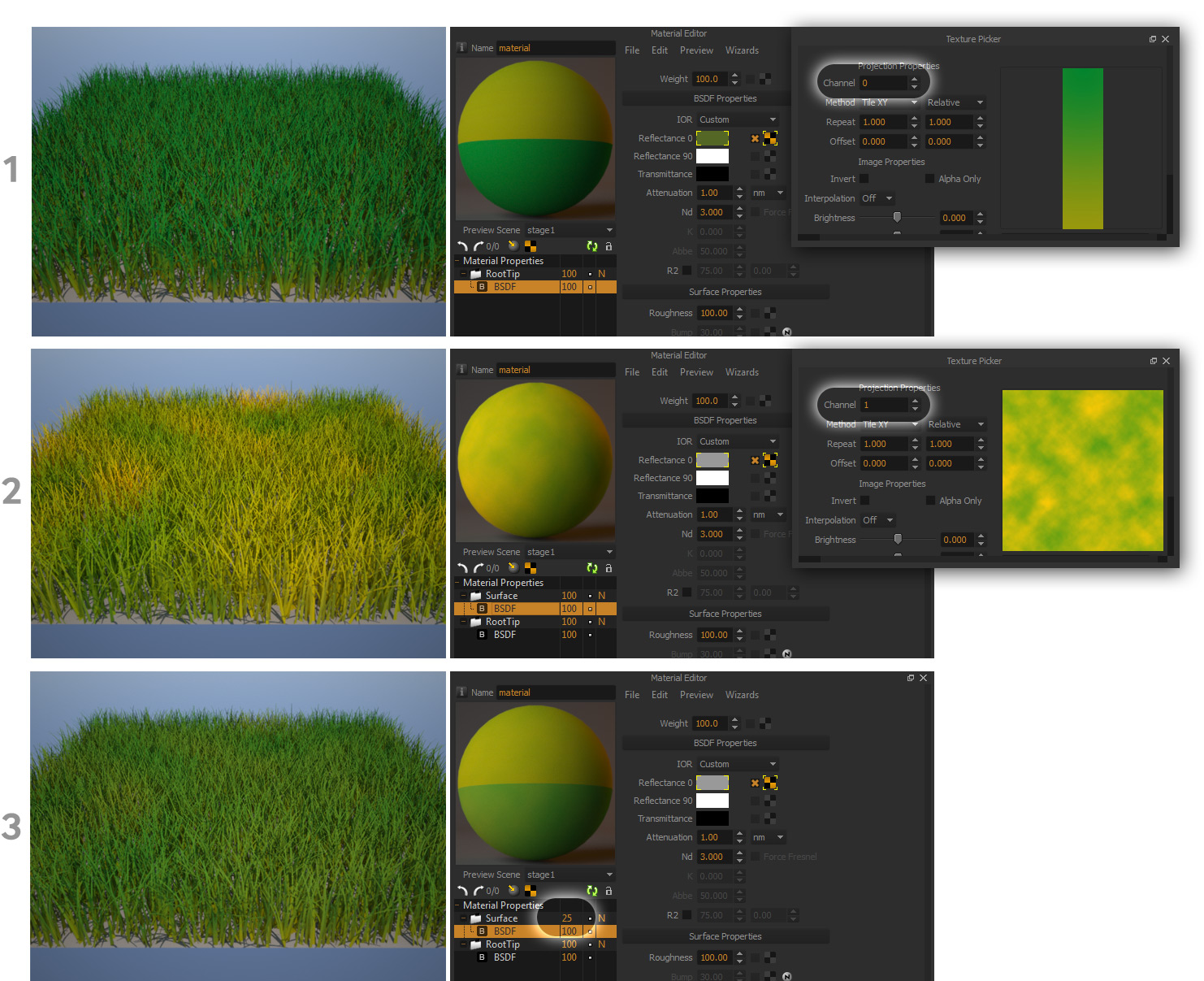
Example 1 - Using a texture in the UV 0 channel (root to tip)
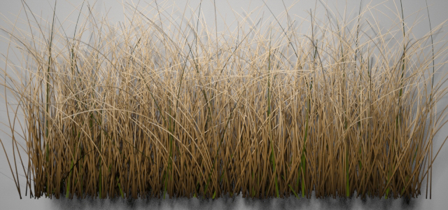
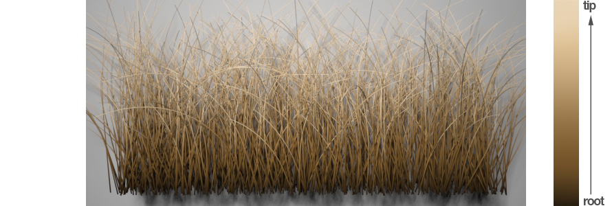
In the image below a texture using UV channel 0 was applied to the reflectance 0 of a BSDF.
Color variation using this gradient texture (right) as the root-to-tip map (channel 0).
The root-to-tip texture is read vertically (only the first column matters)
Example 2 - Using a texture in the UV 1 channel (grass surface)
In the image below a texture using UV channel 1 was applied to the reflectance 0 of a BSDF.
Click image to enlarge
Example 3 - Combining maps using both UV channels 0 and 1 using either 2 BSDFs or 2 Layers
The three series of images below show how you can use two layers to map both the UV 0 and 1 channels at the same time. The top layers BSDF has a texture using the UV 1 channel (surface), and then the Layer opacity is set to 25% so it blends with the bottom layer which has a texture using the UV 0 channel (root to tip)
Click to enlarge
As you can see, there are many different options to map the grass surface, combining these two UV channels. Similar to the example above, you can also map a Layers weight with a texture and set it to use UV channel 1. The BSDFs contained in this Layer can in turn have textures using UV channel 0 (root to tip) which are different from the textures used in the BSDFs of the bottom Layer, and also use different material settings such as thin SSS settings. And why not above these two Layers, add a third one, with a simple color texture (using channel 1) and set the layers weight very low just to add even more subtle color variation across the grass surface.
The Grass Generator parameters
Primitive
Material
Choose which material to apply to this grass modifier. You can either type in the name of a material that is in your scene, or you can drag & drop a material from the Material List panel. See the above section ("Texturing Grass") for more info.
Primitive
Choose the primitive type to render for this grass modifier. See the chapter for more info ("The Grass Primitives").
Points per blade
Sets the number of points to use for the primitive you have chosen See the chapter above for more info ("The Grass Primitives").
Density parameters
Density
Controls the number of blades per square meter.
Density map
Specify a greyscale map to control where the grass will grow. Fully white areas will have the maximum number of blades you specify in the Density parameter. Fully black areas will have no blades.
Seed
This number is used to generate the random distribution of the grass blades. If you use several grass extensions on the same object, make sure the seed number is different for all of them to avoid several grass blades growing from the same location.
Length parameters
Length
The length of the blades in centimeters.
Length map
Load a greyscale map to control the height of the grass over its growth area. Fully white areas will have the maximum length you specify in the Length parameter. Fully black areas will have no length.
Length variation
Randomize the length of each blade, specifying the range of possible length values as a percentage of the nominal Length parameter. For example if Length is set to 10cm and Length variation is set to 50%, the length of the blades will be randomized between 5cm and 15cm.
Width parameters
Root radius
Specify the width (or radius, in the cylindrical grass) in millimeters of each blade at its root.
Tip radius
Specify the width (or radius, in the cylindrical grass) in millimeters of each blade at its tip.
Angle parameters
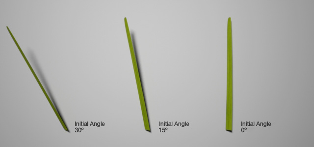
These parameters control the vertical angle at which the blades will grow, based on the surface normal of the geometry the grass is applied to. A setting of 0 degrees means the blades will grow straight up from the surface. CHANGED IN MAXWELL V3.2
Different values for Initial Angle
Grow Towards World-Y - NEW IN MAXWELL V3.2
This percentage allows you to define if the main growing direction of the blades will:
- Grow completely vertical towards the world-Y axis (when set to 100%) like the natural phototropism in plants, no matter the ground surface orientation
- Grow perpendicular to the "ground" surface (when set to 0%)
- Grow at any value in between
The rest of the angle parameters will be applied after this main growing parameter; so the Initial Angle will mean a deviation from this main growing direction, as well as the Initial Angle Variation.
Grow Towards World-Y = 0% Grow Towards World-Y = 100% Grow Towards World-Y = 50%
Example of grass with setting Grow Towards World-Y = 50%. Notice how the blades of grass in the slopes lean up.
Initial Angle
The initial angle at which the blades will grow. It represents a deviation from the main growing direction (perpendicular to the ground surface, towards World-Y or anything in between). Default is 10 degrees. Values range from 0 to 90 degrees. CHANGED IN MAXWELL V3.2
Initial Angle Variation
Randomize the growth angle by a percentage of the initial angle variation. For example if the initial angle is set to 70 degrees and variation is 10%, the angle will be randomized between 63 and 77 degrees.
Initial Angle map
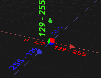
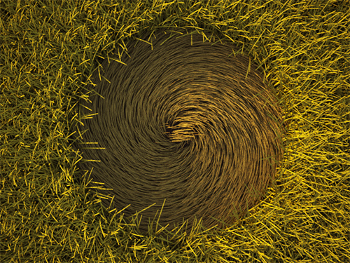
You can use an RGB map which will define the initial angle. The Red, Green, Blue channels in the map correspond to the X, Y, Z axis of the blade. Using a map allows you to make some interesting effects such as crop circles or wavy grass moved by wind. You can create a direction map in an image editor. The Initial Angle parameter is irrelevant when using an Initial Angle map, but the Initial Angle variation still applies, allowing you to add some randomness also when using an angle map.
*note that for the Green channel the lowest value considered is 128, since the blade can't start growing at a negative angle to the surface normal.
For a tutorial on creating an angle map in Photoshop, see the Grass Tutorials page in the Tutorials section. Two Photoshop actions are also available on that page to automatically create an angle map from a black & white drawing.
Bend parameters
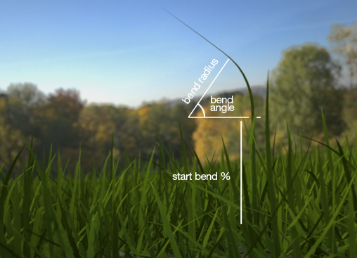
These parameters control the bending of each blade, at what length it starts bending, the angle it bends, and the bending radius.
Bend parameters: Start, Angle and Radius
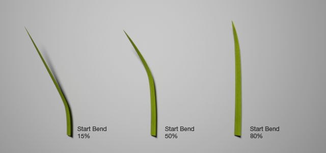
Start Bend
The length of the blade (in percentage) at which the blade starts bending. The blade will be straight until this point, after which it will start bending.
Different values for Start Bend
- Start Bend variation
Randomize the Start Bend parameter of each blade, specifying the range of possible starting bend values as a percentage of the nominal Start Bend parameter.
Start Bend map
Load a greyscale map to control the Start Bend values. This map works as a multiplier for the Start Bend value, so fully white areas will have the maximum value you specify in the Start Bend parameter, and fully black areas will start bending at 0%.
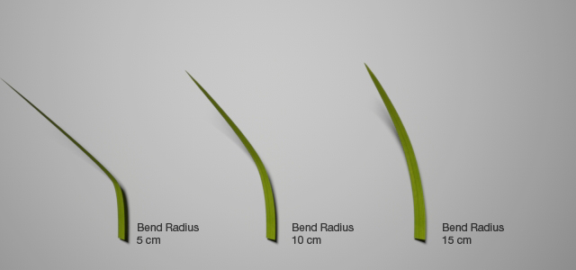
- Bend Radius
The radius in centimeters of the bending.
Different values for Bend Radius
Bend Radius variation
Randomize the bending radius of each blade, specifying the range of possible radii as a percentage of the Bend Radius parameter. For example if Bend Radius is set to 15cm and Bend Radius variation is set to 20%, the radius will be randomized between 12 and 18cm.
Bend Radius map
Load a greyscale map to control the Bend Radius of the grass across its growth area. This map works as a multiplier for the Bend Radius value, so fully white areas will have the maximum radius you specify in the Bend Radius parameter, and fully black areas will have a radius of 0cm.
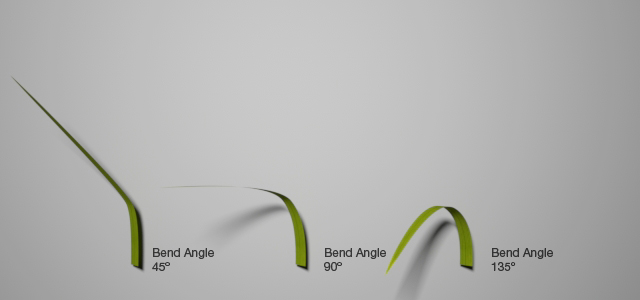
Bend Angle
The bending angle in degrees.
Different values for Bend Angle
Bend Angle variation
Randomize the Bend Angle parameter, specifying the range of possible angle values as a percentage of the Bend Angle value. For example if Bend Angle is set to 80 degrees and Bend Angle variation is set to 50%, the bending angle will be randomized between 40 and 120 degrees.
Bend Angle map
Load a greyscale map to control the Bend Angle at different areas of its growth surface. This map works as a multiplier for the nominal Bend Angle value, so fully white areas will have the maximum angle you specify in the nominal Bend Angle parameter, and fully black areas will have an angle of 0 degrees (no bending).
Cut Off parameters
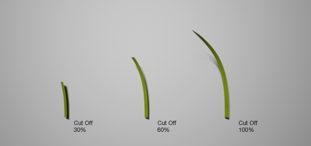
The Cut Off feature allows you to cut the grass as if it were mowed, producing and abrupt cut.
Different values for Cut Off
Cut Off
The length of the blade (in percentage) at which the blade will be cut. The blade grows as usual until this point, after which it will be cut. A value of 100% will let the blade to grow up to its nominal length (no cut at all), while a value of 0% will cut the blade at its very birth (at zero length).
Cut Off variation
Randomize the cut length parameter of each blade, specifying the range of possible cut values as a percentage of the Cut Off parameter. For example if Cut Off is set to 60% and Cut Off variation is set to 50%, the blades will be cut at a random length between the 30% and 90% of their length.
Cut Off map
Load a greyscale map to control different Cut Off values at different areas of the growing surface. Fully white areas will have the maximum Cut Off value you specified. Fully black areas will have a Cut Off value of 0 (cut at zero length).
Grass cut using a cut-off map
Level of Detail parameters
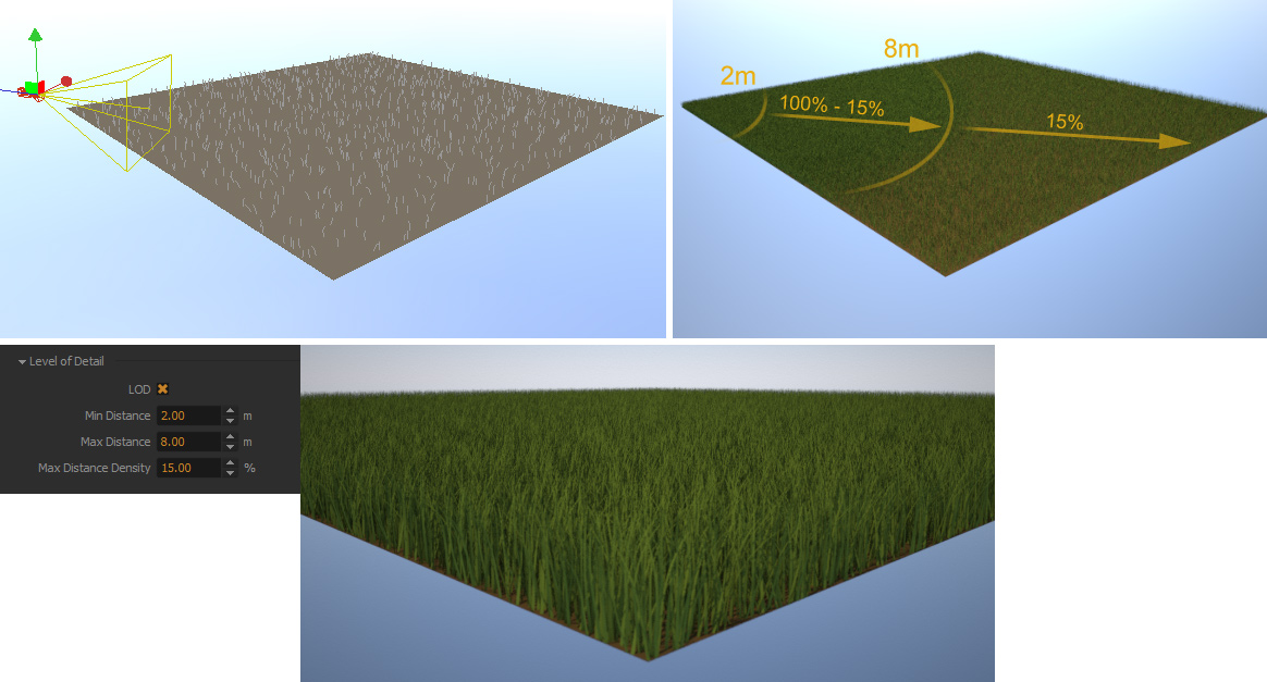
This option allows you to optimize your scene by rendering more blades near the camera and gradually less blades as the distance from the camera increases. The LOD allows you to save RAM when rendering and can be very useful especially for scenes where the camera is placed closer to the ground and looking away towards the horizon. In the example below it's hardly noticeable that only 15% of the blades are rendered after a distance of 8 meters from the camera.
Note that the LOD will be applied to the active camera in the scene.
Min Distance
The distance from the camera where the LOD won't have any effect. 100% of the blades will be rendered in this distance, as specified in the Density parameter.
Max Distance
The distance at which the blade density will have reached the density specified in the Max Distance Density parameter. Between the Min Distance and the Max Distance there is a falloff in the number of blades, until they reach the Max Distance Density.
Max Distance Density
The number of blades per meter you wish to have when the Max Distance is reached.
In this example, between 0-2 meters from the camera, the full amount of blades will be rendered. Between 2 - 8 meters, their number will gradually diminish from 100% to 15% (until 8 meters from the camera is reached). After 8 meters and further, only 15% of the blades will be rendered. Click to enlarge the image
Display parameters
These parameters only affect the Studio viewport display and not the render. It is useful to optimize the viewport speed.
Display Percent
The percentage of blades to show in the viewport.
Display Max. Blades
The maximum number of blades to display in the viewport.
Adjusting the grass display settings to display just 10% of the generated fibers in the viewport (screenshot from Studio)
