...
- Select a node and open a parameter from its → “Node Params” panel.
- Right-click on the parameter and choose “Edit Curve...”. The → “Curve Editor” appears.
- Double-click on a free area of the canvas to create a key.
- Set the exact frame and parameter value with the two input fields (see image).
- Repeat this process until all frames are set.
...
- Enter the expression to the appropriate parameter field,e.g.
=2+sin(t*3)*2.5(mind the = operator!) - Alternatively, right-click on the circle and choose “Edit Curve...”
- Then, go to the empty line at the bottom of the appearing “Curve Editor” and enter the → expression, e.g.
2+sin(t*3)*2.5
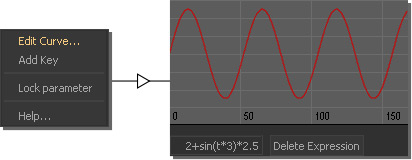
- You will see that the circle turned green and has two black lines.
- Click on the parameter's "+" symbol to open the slider section. There you will find green dots for every expression-driven parameter.
- Right-click on the green dot and choose “Show Expression”. Now it is possible to edit the expression in the parameter's field without having to use the → “Curve Editor”.
- Switch back to the current value with “Show Value” from the right-click menu.
...
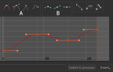
When you right-click on a circle/dot choose “Edit Curve...” to open the → “Curve Editor”. There you can
- create, delete, position, and refine keys
- (multi-)select keys and copy/past them to other curves
- extend curves
- change the key type to → linearto linear, TCB, Bezier, stepped or combinations of all modes (A)
- break, unify, and flatten tangents (B)
- change the curvature, create ease-in and ease-out effects
- add → expressions.