...
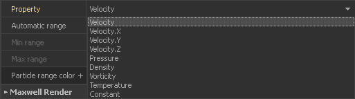
- Selected emitter/domain > Node Params > Display > Property
- “Vorticity” is not calculated by default and therefore you will only get a uniform colour.
- To make it visible it has to be enabled before the simulation starts:
Emitter > Node Params > Particles > Compute Vorticity
Hybrido domain > Node Params > Particle Channels > Vorticity
Textures
| Info |
|---|
| Textures and shaders can only be seen with the “Flat” (9) or ”“Smooth” (0) shading modes. |
All objects provide a texture channel:
- Selected object > Node Params > Texture > Load Texture
- Valid formats are BMP, TGA, JPG, PNG, TIF.
- Only diffuse maps are accepted. Bump maps, normal maps or other types will not have any effect.

There are also parameters which can be controlled with maps, for example “Particle friction” or “Roughness”. Those parameters have a small chessboard icon:
- Right-click on the parameter and choose “Load Texture”.
- A new dialogue appears where you can make your settings.
- Please note that this feature requires an RGB image. Then you can select which channel you want to use for controlling the parameter.
- Image-controlled parameters are displayed in purple.
- There is also complete workflow guid about how to use this feature: → "Quick Start Workflows - Parameter Maps".

Objects also support wet-dry maps (see → "Quick Start Tutorial - WetDry Map Creation" ), RealWave surfaces can have foam maps, and meshes are able to carry displacement maps from → HyFLIP simulations. Despite of all these different maps, a node can only display one map at a time, but you can browse through these textures under
- Selected node > Node Params > Display > Texture
- If you work with imported objects RealFlow will read their UV coordinates and use them for applying the texture(s).
- This means that you have to care for proper UVs in your 3D program. If the UVs are wrong in your 3D application then they cannot be correct in RealFlow.

Shaders
With meshes you also have the option of applying OpenGL shaders:
- Selected mesh node > Node Params > Display > Shader
- The “Transparent” shader supports an environment map. This way it is possible to create realistic previews with reflections.

Particle meshes provide another, maybe more interesting, option: the visualization of channels. A channel is a fluid's property. Typical examples are velocity, pressure, or vorticity. When such a channel has been calculated and saved with the mesh then it can be visible in the viewport:
- Selected mesh > Node Params > Channel > Enable the channel(s) you want to see
- Create the mesh (sequence).
- Selected mesh > Node Params > Display > Particle Channels
...