This extension actually consists of 4 types of volumetrics:
- "Constant density" - creates a cube-shaped volumetric area in your scene which has a constant density. This is useful for very large atmospheric haze effects for example.
...
- "Particle based" - this lets you use a particle simulation to define the volumetric density. You can either use particles directly in supported applications (such as Maya, 3ds MacMax, Cinema4D, Softimage), or load an external particle file in several formats (.abc, .bin, .pxy, .prt, .rpc).
- Volume file based - this works currently with the OpenVDB file format which is a format that describes a volume based on voxels and is not particle based. Usually, these types of files can be created with RealFlow, Houdini, Maya. The advantage of using this format is that you can store very detailed and large smoke/explosion simulations without the need to store billions of individual particles.
...
| Info |
|---|
Any Maxwell material (except emitters) can be applied to the volumetric object (or particles), but generally a normal lambert material works just fine. |
How to use the Maxwell Volumetrics extension
The details will depend on what plugin you are using, or whether you are using Maxwell Studio, but in general, you add this extension as an object to your scene and it will be represented by a cube (in the case of Constant density and Noise3D), points that show the particle cloud in the case of Particle based, and a cube bounding box representation in the case of the Volume based type. Please see your specific plugin documentation for details on how to add an volumetric object to your scene. You then apply any Maxwell material to this object.
...
This will actually be a separate cube-shaped object in your scene, which can be manipulated like any other object (translated, rotated, scaled). The volumetrics will be visible only inside this cube shape. Please see your plugin documentation for specifics on how to add a Constant Density object to your scene. In Maxwell Studio, you can add it by right-clicking in the Object panel and choosing Create Extension Object>MaxwellVolumetric.
...
As mentioned above, this type also uses a cubic shape to define the volume , but adds a 3D procedural noise to add some variation to the density. In the following examples, the density has been set very high to make it easier to see the changes to the noise parameters.
...
Create larger or smaller sized noise detail. In other applications, this parameter is sometimes referred to as "wavelength".
...
Octaves from left to right: 1,2,3. Detail level was kept at 3 and Persistance was kept at 0.6 for all renders.
| Excerpt | ||
|---|---|---|
To better visualize how the Octave parameter affects the noise pattern, lets let's look at it through a 2D cross-section:
5 octaves of noise shown individually,and then added together to form the final noise. Notice how the final noise retains some of its original shape from the first octave (in this case a medium Persistance was used, see below) PersistanceThis parameter controls how "persistantpersistent" the noise is through each octave. With a high setting, the initial noise pattern quickly disappears, while the frequency of the noise increases:
Example of using 5 octaves, and a high Persistance such as 0.9 -notice in the result how the initial noise pattern is not really present anymore because of the high frequency/small wavelength noise On the other hand, if the Persistance is very low, the noise pattern will dissipate very quickly with each octave:
Still using 5 octaves, but a small Persistance such as 0.1 - notice how the initial and final noise patterns are largely the same, no matter how many octaves you specify.
|


...
| Info |
|---|
Particle file formats currently supported
For more information about these formats, please see this page in the RealFlow documentation. |
...
Radius multiplier
For any density to be visible in the render, the particles must, first of all, have a certain initial radius. This is determined by you when you create the particle simulation, depending on which scale you work in, and at what scale you have exported your scene to Maxwell. This parameter lets you multiply that radius - in case the particles have a too small radius, or you want to change the look of the volumetric. Increasing this parameter has the effect of making a more "puffy" less defined look.
...
| Warning |
|---|
Be careful not to raise this parameter too high. If you start noticing that the scene voxelisation voxelization time increases a lot, it usually means the radius multiplier is set too high |
...
You can increase or decrease the amount of density that each particle will contribute with using this parameter. Note that the final density will still be limited by the "Max final density" parameter.
...
Values of 2, 5, 100 ("Max final density" parameter was kept at 35 for all renders)
Min final density
The minium minimum density in a particular cell of the volumetric object. In most cases, you should leave this value at 0 as you don't want any visible density where there are no particles.
...
The cell size should be considered the "resolution" of the volumetric object. The parameter uses a real-world unit of 1m. The smaller the cell size, the finer the resolution. Just as a bitmap image can reveal more detail when zoomed in if it contains a lot of pixels. The cell size parameter is necessary in order to keep the RAM usage under control. So the final RAM consumption is not influenced by the number of particles in your simulation, but instead on the number of cells which are created at render time, which define the resolution of the volumetric object.
| Warning |
|---|
Decrease this setting carefully as very small changes can cause your RAM consumption to increase a lot. |
How cell density is determined
It is important to understand that what you finally see in the render is the contribution of the density of each cell, NOT particles directly turned into density. So how is the amount of density for each cell determined? Each cell looks from it's its corners into the cell to see how far away a particle is in regards regard to each corner. Depending on the particle radius, density multiplier, and max final density - some density may be shown, or nothing at all.
...
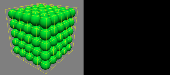
A 10cm large cube of particles, where each particle is 2cm in diameter, and each cell is 1cm in size (setting of 0.01). The cells are small, so a smaller search distance inside the cell is needed to find a particle, thus we see some density created in each cell in this case. Notice that we are not seeing the round shape of the particles, but rather the square shape of each of the cells. The cells (the "resolution") would need to be even smaller to start mimicking the round shape of the particles.
Here the cell size was increased to 2cm. Since the distance each cell has to search has increased, nothing appears in the render. We could raise the Radius Multiplier in this case to make the particles bigger, or lower the cell size again to make some density reappear. We could in fact also raise the cell size even more, and some density would appear again. See the next illustration for why this happens.
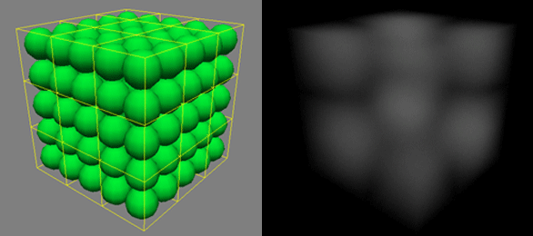
Now the cell size is 3cm and we start seeing some density again. This can seem very unintuitive at first, but looking at the grid of cells, it is clear that now some corners of some cells are actually closer to a particle compared to when the grid was set to 2cm. So we start seeing a very rough, square representation of these particles , because the cell size is so large.
Density multiplier as a "falloff"
...
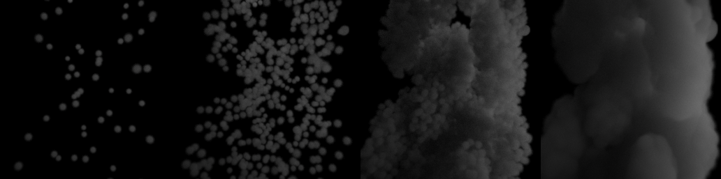
All renders with a cell size of 2mm, Max Final Density at 500. Only the Density Multiplier changed: 10000, 3000, 1000.
This series of images is ment meant to show two things. First, that with a small enough cell size, each particle can be very well defined (in these renders the cell size was reduced to 2mm (a setting of 0.002). Second, how the Density Multiplier parameter can act as a sort of falloff between areas of density and no density. The Max Final Density was 500 for all renders. You can see that as the Density Multiplier decreases, there is a larger area of falloff between no density to the areas of maximum density. When the Density Multiplier is very high, there is a very sharp falloff, making the volumetric shape have much sharper contours.
Extra particles
This parameter adds extra particles around the simulated particles. This way, a much lighter simulation with a small amount number of particles can produce a more dense cloud by multiplying them at render time. The new particles are affected by the speed of the original ones, so your particles must have some speed or this parameter won't have any influence. Note that more RAM will not be used if you create extra particles, this depends again on the final number of cells created by the cell size parameter. If you do use a high dispersion though, it is likely that more cells will be created since the total bounding box of the particle cloud will increase, thus increasing the amount of RAM needed for rendering.
 Extra particles set to 0, 10, 200.
...
The dispersion was set to 0.1 (10cm) in this case. RAM usage only very slightly increased even with 200 extra particles per particle. The
...
rightmost image shows the particle radius increased to avoid seeing the individual particles.
Extra particles dispersion
...
The new particles can be generated randomly inside a sphere based on the position of the "parent" particle, or inside an ellipsoid with this value of eccentricity. The ellipsoid is aligned along the direction of the parent particles' speed.
Motion blur factor
You can control the amount of motion blur visible on the particles, separately from the scenes scene's main motion blur settings. If you want the particles to look blurrier as they move, increase this parameter.
...