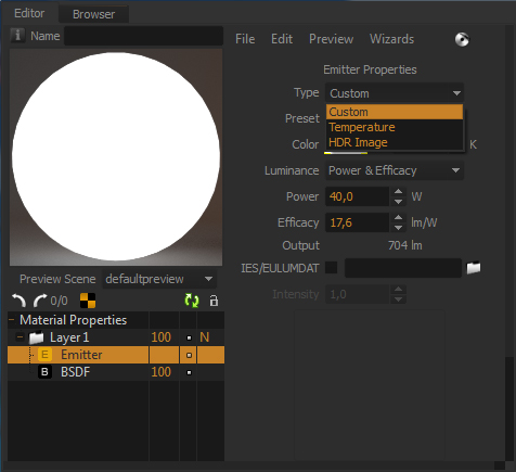
Emitters in Maxwell Render are part of the material system. An emitter material should be applied to the geometry you want to emit light from. The emitter geometry needs an actual surface area; it is not possible to apply an emitter material to a Null object for example.
You can create a geometry (a bulb, a tube, or just a simple plane), and apply a Maxwell material and add an Emitter component to it. You now have an object that is lighting your scene. To optimize your scene, try to use low-polygon geometry for your emitters. A single polygon plane will do in most cases.
Emitter Materials are defined in a very intuitive way, using real world values like watts or efficacy.
| Note |
|---|
Maxwell Render will use the normals direction of the geometry to decide in which direction to emit light from the geometry. Make sure the normals of the emitting geometry is pointing in the direction you intend. If your emitters don't seem to be emitting any light in your scene - the normals direction should be the first thing to check. You can flip the normals in your 3D application if the direction is wrong, or in Maxwell Studio, select the object, go to the Object parameters panel (Appearance section) and click the Flip button. |
Emitter types
Your emitter can be defined in three different ways: Custom, Temperature and HDR Image.
Emitter types
Custom
This option allows you to set the Color and the Intensity of your light separately. Color can be set in RBG, HSV or XYZ scales, or correlated to a Kelvin value. Intensity (or Luminance) can be set in a number of different ways (see the Custom Emitters page). You can also specify an IES/ Eulumdat file to light your scene, using measured lighting data for different lighting fixtures. These files are provided by many major lighting manufacturers.
...
